
ERV Project Brief

What  how and how much


GREENWAY ERV PROJECT 

Interesting ERV project This is my own record of my ERV home ventilation project. By way of this blog I hope to share my wee project with people who are interested and keep a record for myself as well. The cost is considerably less then HRV's and ERV's on sale in New Zealand and it's been a really interesting project the study up on.

A BIT ABOUT GREENWAY

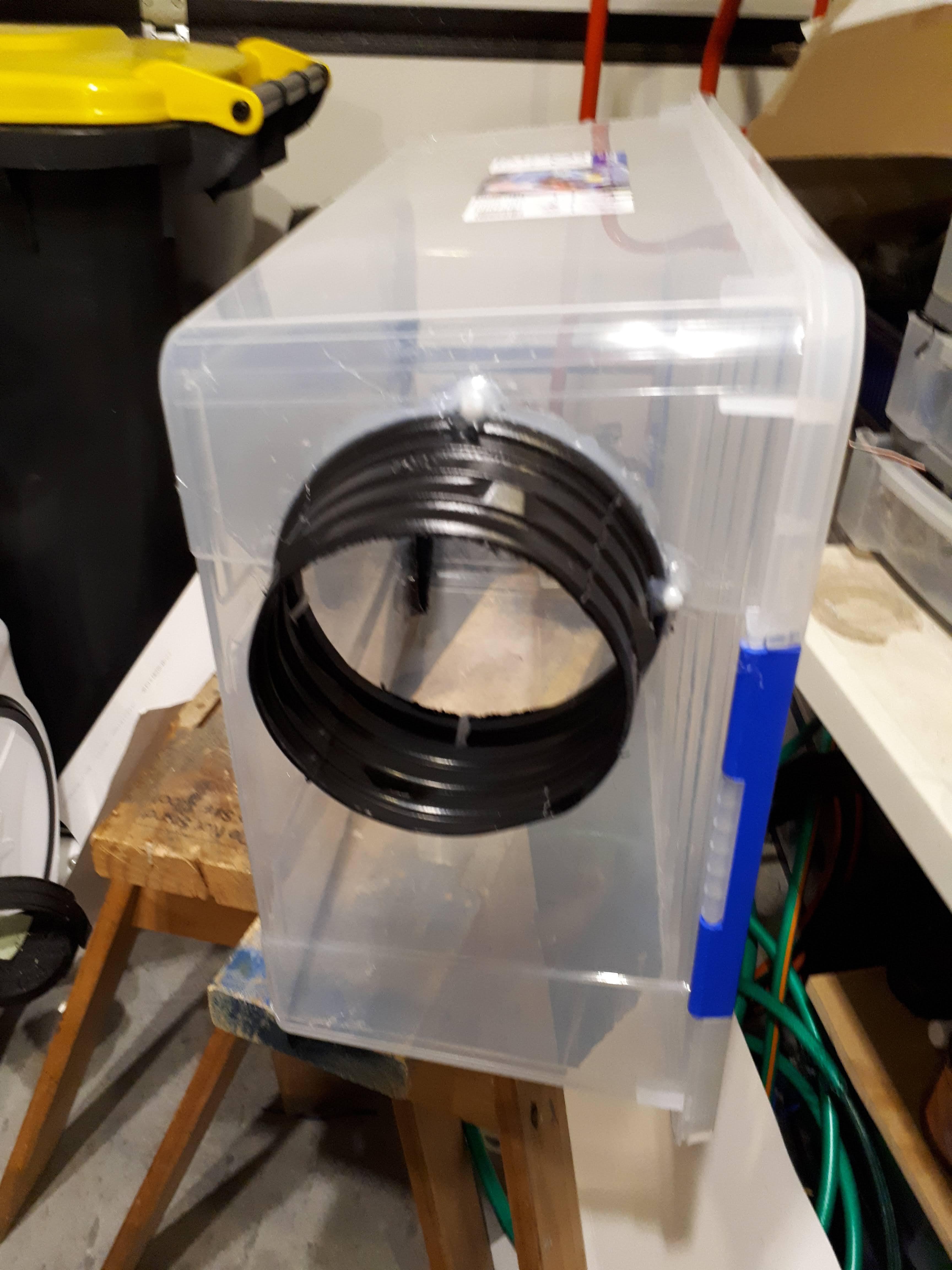
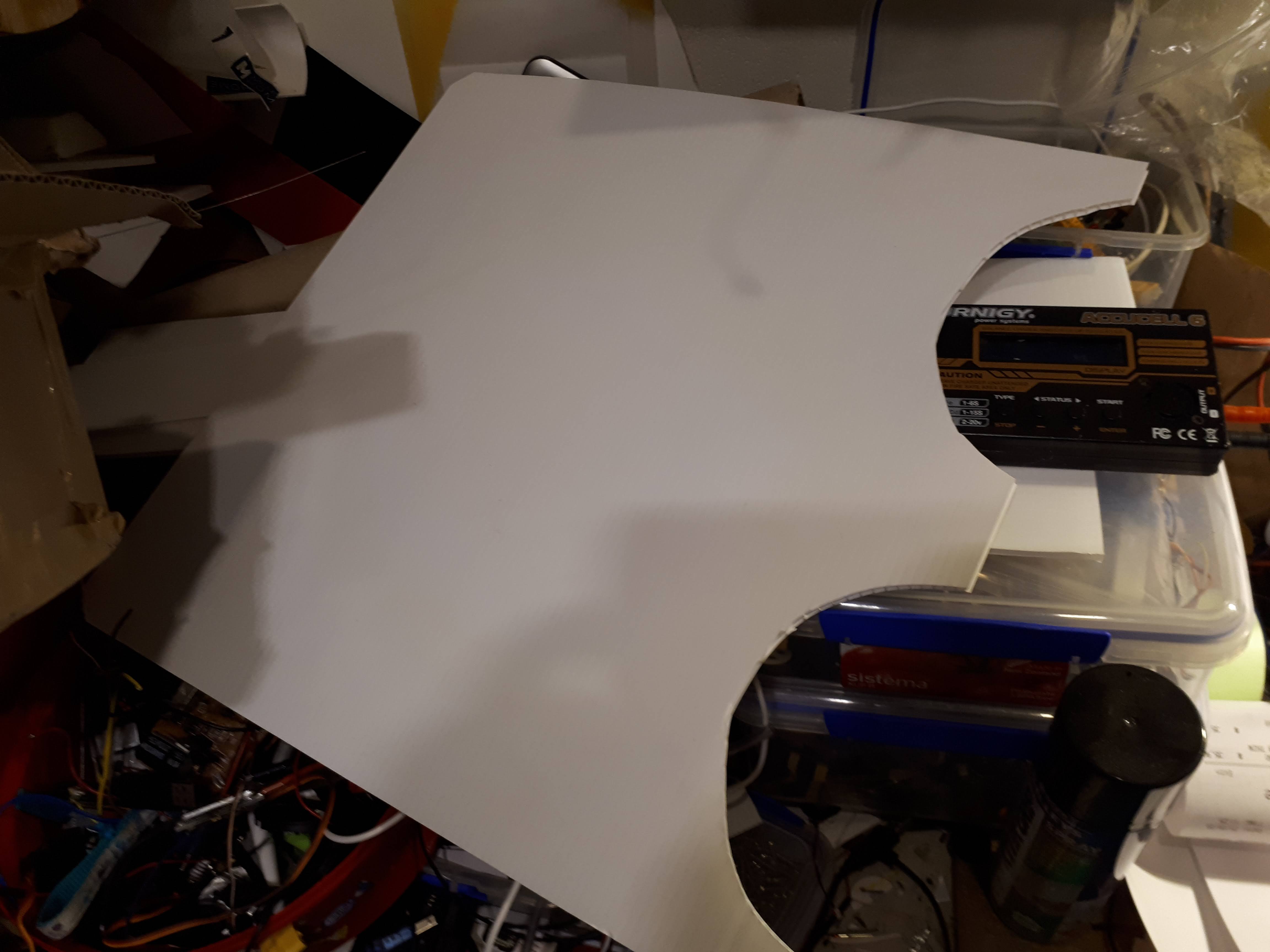
This is a blog about my ERV project. My background is in industrial automation and control systems and I have recently got interested in home automation. Our system is based on Arduino, Hubitat Elevation and  MQTT. I have a gaggle of devices like Sonoff's and Arduino using MQTT, Thinger and occasionally Node-Red for experiments mostly. We wanted a low cost 150 mm system for our home using the most cost-effective parts we could find. I know its made of Coroplast and tape but if it works as I hope it will I will re-engineer some of the components in more durable materials.

THE PROJECT

There are 2 position-controlled valves 3 main fans, and 4 boost fans. Experiments show with a 6 Meter 150 mm duct and the main fan and boost fan at maximum we can get a flow in excess of 8 Cubic Metres per Minute.

The Goal

  • To create a cost effective ventilation system for our home
  • Reduce or eliminate condensation
  • Provide filtered clean air
  • Balance heating in the home
  • Determine best option ERV or HRV
  • Utilise Hubitat Elevation home automation hub


Roll your own for NZ$1500 https://greenwayerv.blogspot.com/ its eliminated condensation totally, even in September with frosts in NZ. The house is 5 years old so not many leaks, a balanced ERV seemed like my best option. The pollen filters also improve allergy symptoms in spring here too. Energy bill for September NZ$90 So economical, even temperature throughout the house.


What to do

 Looking at the specifications of propitiatory systems it seems that the fans are nothing special. They typically use Axial flow fans with AC voltage motors around 60 Watts seems suitable for our house. In order to allow me to do this without an electrical certificate my system is entirely 12 volt. 


The fans I have are pretty quiet to so it seems like win win to me less that US$30 each for the 60 W devices and US$16 for the boost fans.

Computer fans are a good low cost option. Quiet long lived and they have built in speed controllers too.


I am using two fan types in the system. I bought them cheaper than this


Specifications:

-- Size: approx. 120*120*38 mm

-- Voltage: 12(V)

-- Blast Capacity: 280.38CFM

-- Current: 5.0A

-- Rotate Speed: 7500CPM(r/min)

-- Noise Level: 64DBA

-- Wind Pressure: 24.60 mmH2O

-- Bearing: High precision double ball bearing

-- Operating Temperature: -10℃ ~ + 70℃

-- Storage Temperature: -40℃~+70℃

-- Power range: Plus or minus 15% of rated power supply

-- Insulation Resistance: More than 500 megohm

-- Fan Frame: Injection molding, PBT+ 30% glass fiber + VO class flame retardant.

-- Fan Blade: Injection molding, PBT+ 30% glass fiber + VO class flame retardant.

-- Suitable for workstation cooling/server CPU cooling.


Specifications:

Size: approx. 120*120*37 mm

Voltage: 12(V)

Blast Capacity: 267CFM

Current: 1.85A

Rotate Speed: 6500RPM(r/min)

Noise Level: 70.5DBA

Fan Interface board: 4 pin interface

Bearing: High precision double ball bearing


The larger capacity fans are used in the ERV heat exchanger and are the main fans for the system.  The others are lower powered and used as inline boosters or filter fans.


There is an additional 60 Wall fan in the exhaust 2 way Turbo valve to help boost exhaust flow in a purge situation. e.g. curry button

Popular Posts

The Heat Exchanger

  Under construction It took around 6 hours to layer the core Based on a 60 Litre Sistema box with a 400 X 400 X 350 6 mm Coroplast core. The fan speed controller is mounted on the end so it takes a 12V 10 Amp supply from the power system and 2 analogue 0 to 5 V signals for speed demand. The pink foam is a NZ$12 exercise matt which insulates it for both sound and heat quite nicely. 60 Litre Plenum on the vent side See  https://greenwayerv.blogspot.com/2020/10/we-added-60-litre-plenum-on-vent-side.html

Home Ventilation Heat Exchanger


The Experiment

First things first an experiment. I had been looking around at various homemade ERV core designs and eventually decided to try a Coroplast design. The experimental core was tiny 12 X 12 X 12 cm  using 3 mm Coroplast Nice isn't it :) 20 80 mm PC cooling fans at a fixed speed four temperature probes. Here is the full scale one around 40 X 40 X 35 cm using 6 mm Coroplast A Wemos D1/R2 for instrumentation sending temperatures via MQTT to Node-Red. I'm was not totally convinced by the numbers but it did definitely exchange significant amounts of heat. I checked the calibration and it was good compared to my multi-meter TC probe. In any case it seems to work even at such a small scale. Never did understand why it seems to gain more heat that it lost from the exhaust steam, checked for leaks there were none. Any way  a hairdryer experiment showed it worked and heat was transferred too so I was happy that it would probably work at a larger scale.

Heat Exchanger Low Ambient 86% Heat Recovery

  Drop on exiting air 2.9C Heating of incoming air 2.5C So 86% of the heat recovered

The ERV Data Acquisition System

  Progress over the weekend with the ERV DAS The 999's are me testing the sensor disconnected response. I have a Pitot tube left over from an RC plane I think I might put it in the inlet air stream Pin assignment in the Arduino sketch DHT dht[ 4 ] = {DHT( 4 , DHTTYPE),DHT( 0 , DHTTYPE),DHT( 2 , DHTTYPE),DHT( 14 , DHTTYPE)}; There are 4 DHT22's inside heat exchanger lid, shown below. Sensor locations Arduino code #include < Arduino_JSON . h > #include < ESP8266WiFi . h > #include < MQTT . h > #define LED_PIN LED_BUILTIN //LED_BUILTIN is built in LED #include "DHT.h" // Uncomment whatever type you're using! #define DHTTYPE DHT11 // DHT 11 //#define DHTTYPE DHT22 // DHT 22 (AM2302), AM2321 //#define DHTTYPE DHT21 // DHT 21 (AM2301) WiFiClient net ; MQTTClient MQTTclient ; const char ssid [ ] = "Network" ; const char pass [ ] = "DF@#$%" ; // the IP address for the MQTT server char MQTTip [

Drivers and Arduino Sketches for ERV Fans Control Testing

  The Hookup For proof of concept seems to run reliably in the lab. I don't want to be up and down ladders to make update I intend keeping the control system in Hubitat so I can tinker to my Hearts content. Boost fan PWM control as well as start relays. The valve position is a separate driver and device in Hubitat, This will use one of the PWM Four boost fans in the ducts for each room inlet. One fan in the two way turbo exhaust valve. The valve position is a separate driver and device in Hubitat, This will use one of the PWM pins on the Wemos and its analogue input for the position pot Hubitat Valve Position Driver import groovy.json.JsonSlurper metadata { definition(name: "Greenway ERV Turbo Valve", namespace: "Greenway", author: "Nick Goodey") { capability "Initialize" capability "Switch" capability "Switch Level" command "on" command "off" } preferences { section("Device&qu